
By Mike Jahrig KG5P
(Part 3 of a series)
Last time we discussed investigating the properties of low pass and high pass filters using the Nanovna. Today we will discuss 2 additional common filter types, the bandpass, and bandstop (sometimes called notch) filters.
Below are the filter use instructions from my Yaesu Ftdx-3000 manual.
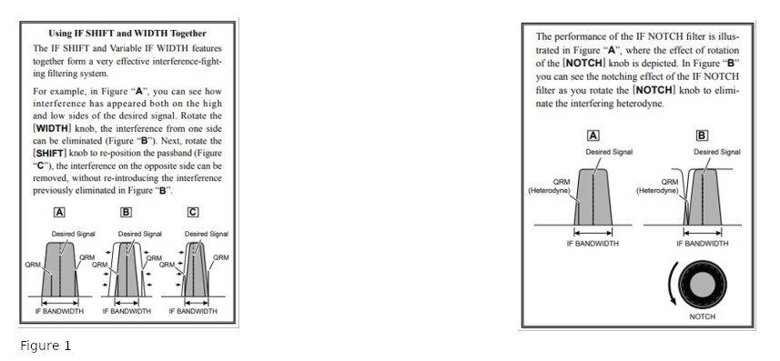
As you can see, the band-pass filter on the left can be adjusted to move the IF passband up or down in frequency so it will reject interfering signals like QRM or heterodyne below and above the passband settings. On the right is the notch or bandstop filter. This allows you to put a “notch” in the passband somewhere that nulls out an undesired signal but retain the original passband limits. You probably have one or both of these filters on your HF rig.
In my case, I also have a very sharp peaking filter for CW only that can be set to provide a very narrow audio bandwidth, like 50 Hz. Many HF rigs, mine included, also have a “roofing filter”, that has an adjustable bandpass from 300 Hz to 15 kHz in the 1st IF stage that can reject interference outside the “roof.” Typically the width and notch filters are installed in the 2nd IF stage, and the audio peaking filter is where the name implies.
I used LTspice to draw the schematics. Get a free copy here. This is also a circuit simulator that I used to investigate their behavior. It includes a Bode (rhymes with “goaty”) plotter feature that I will use.
Band-Stop Filters
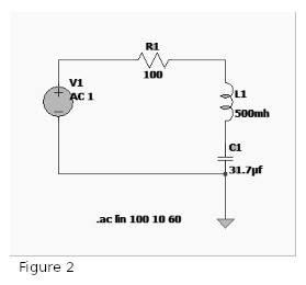
First, let’s look at a bandstop filter below because it is the simplest. Remember how inductive and capacitive reactance work. As supply frequency increases, inductive reactance or opposition to current flow increases. And as frequency increases, capacitive reactance or opposition to current flow decreases. Most importantly, when the inductive and capacitive reactances become equal, they cancel each other out and the circuit provides no opposition to current flow at that frequency.
Above any frequency, the inductor provides the opposition and below the capacitor provides it. So, the circuit is a bandstop filter. At the frequency where the reactances are equal but opposite, they mutually cancel each other; the inductor and capacitor series combination passes all the current to ground, and that frequency is eliminated from the output.
Now let’s see what happens within the filter:
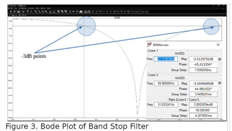
Here we see that the “notch” or bandstop lies between the -3dB points. Also, the Bode plot shows this occurs between 27 andabout 59 Mhz. Thus, that range is “stopped out” or notched. Hence the name “notch filter.” The Bode plot tells us the depth of the notch is around 27Mhz. This filter might be good for eliminating annoying CB interference on the low end of 10 meters.
Band-Pass Filter
Next, let’s look at a bandpass filter.
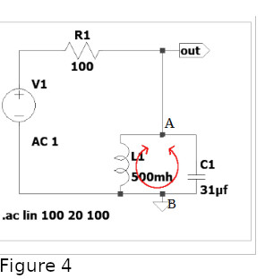
Note the parallel inductor and capacitor. This combination, by itself, has some very interesting properties. It is found everywhere in electronic circuits. Often called an LC tank circuit, it causes the current through it to resonate in phase with the supply AC voltage. Additionally, there is a large circulating current between the inductor and the capacitor as the energy is alternatively swapped and stored between magnetic and electric fields. If not for ohmic losses, this would continue forever, and no current or energy would be drawn from the supply.
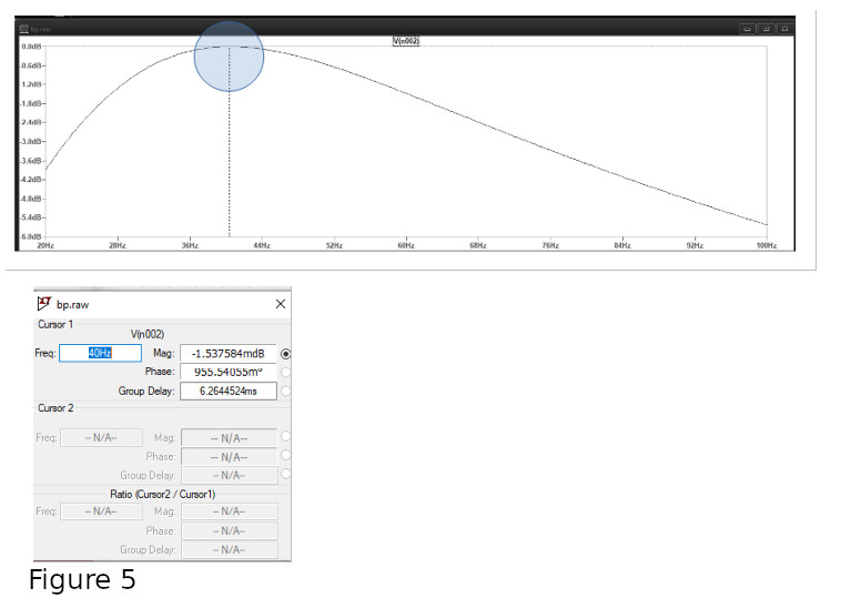
Consequently, at resonance, the impedance between points A and B is at its maximum value. This results in no current flow between A and B. Thus the LC combination is effectively an open circuit. All supply current appears at the output, with none shunted to ground. Below is the LTspice Bode plot. You can see the peak of the filter (the least amount of attenuation) occurs at 40 Hz.
The Bode plot also allows us to determine the -3dB half-power points. By moving the cursors to those points, we determine the cutoff frequencies.
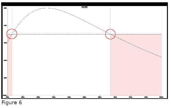
Here we see that they are about 22.2 and 73.5 Hz respectively. This means that those frequencies below and above are attenuated by at least 3dB (shaded area.)
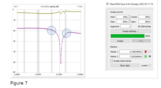
Now let’s look at the bandstop filter on the Nanovna. Again, look at the purple S21 LogMag plot. We use this because we want port 2 of the Nanovna to show the output of the DUT, the bandstop filter. If you look at the scaling, the relative bandstop is flat starting around 18dB, so that makes the half-power points, -21dB at 5.3 Mhz (the red marker) and 7.26 Mhz, the green marker).
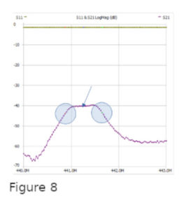
The S21 LogMag plot of the RF Demo Kit bandpass filter is below. As you can see, the -3dB cutoffs occur somewhere below 440.75 and above 441.75 Mhz. Thus, the passband is about 1 Mhz. The arrow points to the center I eyeballed at 441.25 Mhz
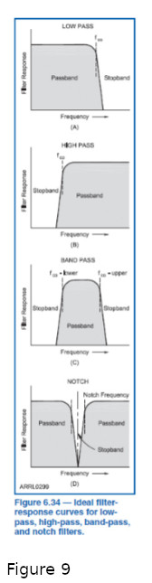
So now we have discussed 4 basic filter types commonly found in amateur radio, lowpass, highpass, bandpass, and bandstop. There are many variations to these in addition to other types of filters.
The summary diagram is from the ARRL Extra Class License Manual, Chapter 6.
You know now more about filters than you will need to pass the General class license exam. There is more about them in the Extra class exam but I won’t get into that here.
But now you can relate the information to your Nano-VNA.
Next time I will root through my junk box for some inductors and capacitors and use the Nano to measure them. Stay tuned to this station.
73 de KG5P
Related Posts
 How To Program Your DMR Radio For The Balloon Single Frequency Repeater
 QRV Tech – March 2025 – Build & Configure a DigiPi
 QRV Tech – February 2025 – A Short Discussion of Coax
 RWK Parks-On-The-Air Outing Coming Feb 15th
 QRV Tech – January 2025 – Intro to Station Grounding
 QRV Tech – December 2024 – Learn How To Model Antennas